Ceramic PCB ManufacturerDate: 2022-12-08
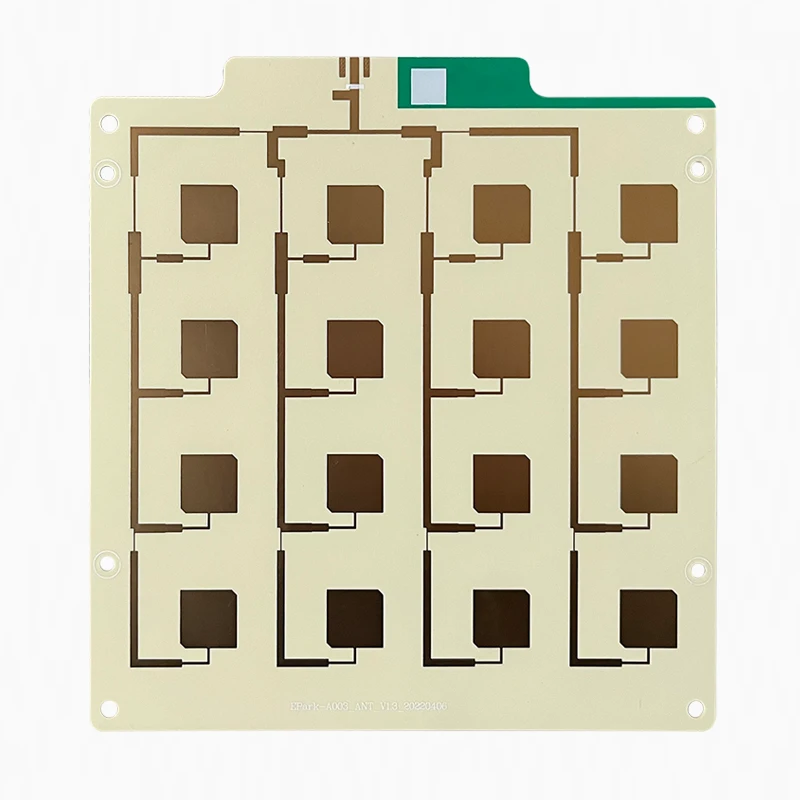
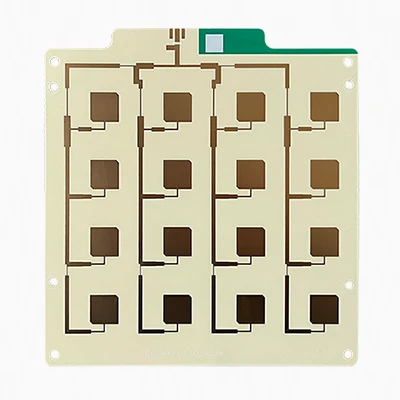
- PRODUCT DETAIL
- TECHNICAL SPECIFICATIONS
The Manufacturing Process of Ceramic PCB
Conventional production methods for ceramic substrates can be divided into four types: HTCC, LTCC, DBC, and DPC.
● HTCC preparation method requires a temperature of 1300°C or more, but the preparation cost is quite high due to the choice of electrodes.
● LTCC requires a calcination process of about 850°C but has poor circuit accuracy and low thermal conductivity.
● DBC requires the formation of an alloy between copper foil and ceramic, and the calcination temperature must be strictly controlled in the temperature range of 1065-1085°C. Because DBC requires the thickness of copper foil, which generally cannot be lower than 150-300 microns. Therefore, the ratio of line width to depth of this ceramic PCB is limited.
● The preparation method of DPC includes process coupling such as vacuum coating, wet coating, exposure development, and etching, so its product price is relatively high. In addition, in the molding process, DPC ceramic sheets need to be laser-cut. Conventional drilling, milling, and punching machines cannot process them precisely to make the adhesion strength and line thickness more accurate.
Benefits of Ceramic Printed Circuit Boards Over Traditional PCBs
There are several advantages to using ceramic circuit boards. They help significantly reduce the final product’s size and weight while improving energy efficiency. High-quality surface finish (due to their flatness), high-temperature resistance and low dielectric constant are other significant advantages. In addition, ceramic boards are durable and wear-resistant, which means they can be used in areas of high mechanical stress. Other favorable characteristics of ceramic circuit boards are as follows.
● Ceramic PCBs are suitable for high component density on a single board because ceramic substrates are purer than glass fiber-reinforced epoxy and FR-4 boards. This means they can accommodate smaller components while maintaining the same mass and footprint.
● Ceramic plates are many times more resistant to high temperatures than FR4. They also have a much higher heat deflection temperature than conventional FR4. This allows the board to perform better at extreme temperatures, which extends its life of the board.
● Ceramic circuit boards are more resistant to moisture than FR4 boards.
● Instead of being made of epoxy glass, ceramic circuit boards are made of ceramic, which is more durable and harder than epoxy glass.
● Ceramic boards are denser than conventional printed circuit boards, ensuring high signal integrity. In addition, these boards are faster and more reliable than traditional circuit boards.
● Because of their rigidity, these boards are less prone to damage, which is usually caused by vibration or drops. They also have minimal flex, so they can be used in high-temperature or high-impact applications.
● Another advantage of ceramic printed circuit boards is their fire resistance. This can make them a good choice for products that need to comply with certain guidelines regarding flammability and heat resistance. Ceramic boards have a high thermal resistance due to their low thermal conductivity. A thin layer of ceramic fibers on the surface of the PCBA prevents heat from flowing into the board, while it protects the conductive wires from cracking if they are exposed to too much heat.
Types of Ceramic Printed Circuit Boards
Three main ceramic PCBs are available in the electronics market, depending on the production method.
● High-Temperature Ceramic PCB
● Low-Temperature Ceramic PCB
● Thick Film Ceramic PCB
High-Temperature Ceramic Printed Circuit Boards
These PCBs are designed for high temperatures and are also known as high-temperature co-fired ceramic (HTCC) circuits. These PCBs are manufactured in a unique way. To create the new ceramics, the process combines solvents, plasticizers, binders, alumina and lubricants.
Once the new ceramic is developed, it is coated and the circuit is traced on molybdenum or tungsten metal. Following this, the circuit is baked between 1600 and 1700 degrees Celsius for approximately 48 hours after lamination. The baking is done in a specific gas environment that includes hydrogen gas.
Low-Temperature Ceramic Printed Circuit Boards
This type of circuit board is designed for low temperatures and is also known as a low-temperature co-fired ceramic (LTTC) circuit. The manufacturing process for low-temperature ceramic circuit boards is different from the high-temperature or HTCC type. First, adhesive and crystal glass are used to make low-temperature ceramic PCBs. Both of these materials are coated with gold paste on a metal board. After this, the boards are cut and laminated. Finally, the circuit is placed in a gas oven at 900 degrees Celsius.
Low-temperature ceramic PCBs have better shrinkage tolerance and less warpage. In short, LTTC will have higher thermal conductivity and mechanical strength than other types, including HTCC. The thermal advantages of LTTC PCBs make them the preferred choice when using heat-free products such as LED lamps.
Thick Film Ceramic Printed Circuit Boards
Manufacturing this type of PCB requires the application of dielectric and gold pastes on a ceramic substrate material. After applying these two pastes, the material is baked at or below 1000 degrees Celsius. Thick film ceramic is preferred because it prevents copper from being oxidized. As a result, ceramic board manufacturers can use interchangeable conductors, semiconductors, wires, power capacitors and resistors on ceramic boards. When manufacturers are concerned about oxidation, they choose this type. The conductor layer of this type of printed circuit board can be thicker than 10 microns but not thicker than 13 microns.
Features of Ceramic PCB
Compared with conventional PCBs, whose base materials are epoxy glass fibers, polyimide, polystyrene and phenolic resins, ceramic PCBs have the following characteristics.
● Excellent thermal conductivity
● Chemical attack resistance
● Pleasant mechanical strength
● Compatible with CTE of components
● Easy to achieve high-density tracing.
The increasing functionality, miniaturization and high speed of electronic devices and the scaling of integrated circuits necessitate more stringent requirements for ceramic printed circuit boards in terms of CTE, thermal conductivity, losses, dielectric constants and bandwidth resistance. It is estimated that there will be an increasing demand for ceramic printed circuit boards with aluminum nitride, mullite and glass-ceramic substrate materials.
Ceramic PCB Application
Industries that require higher frequency connections and good heat resistance can benefit from ceramic PCBs. Key sectors that ceramic PCBs can serve include high-power circuits, chip-on-board modules, aerospace and heavy equipment, automotive, medical equipment, heavy machinery, high-performance transistors and transistor arrays, substrates for solar cells, and other power applications such as DC conversion.
Detailed Comparison of Ceramic PCBs and FR4 PCBs
Ceramic and FR4 substrates are different in many ways. In addition, they offer PCBs with contrasting properties, so let’s compare ceramics with the most popular choice on the market – FR4.
● Cost: FR4 is the absolute winner here as it is almost the most affordable option on the market.
● Manufacturing simplicity: Both printed circuit boards are manufactured using the same technology.
● Material availability: It is difficult to obtain virgin component/ceramic substrates for PCB fabrication, so FR4 is the winner.
● Range of applications: FR4 is well suited for low-cost electronics in almost all industries. On the other hand, Ceramic PCBs are an expensive option for advanced devices.
● High-frequency applications: FR4 is simply unsuitable, while ceramic PCBs offer competitive performance.
● Ease of use: Ceramic PCBs are difficult to access and fragile, while FR4 cannot be packed densely, so there is no winner.
● Thermal performance: Ceramic PCBs can operate at much higher temperatures, do not deteriorate quickly and have higher dimensional stability.
● Water Absorption: Unfortunately, FR4 absorbs up to 2% of its weight, while ceramic PCBs do not absorb water at all.
● Electrical performance: Ceramic PCBs perform slightly better and are a more energy-efficient choice.
● Design freedom: From a design perspective, ceramic PCBs are more versatile because they can accommodate blind and buried microvias.
When to use ceramic PCBs and when to use FR4 PCBs?Allow us to explain.FR-4 is more often produced for low-cost devices operating in normal operating environments (0-40°C), in devices heated to 80°C. Ceramic PCBs are placed in advanced devices that need to withstand extreme temperatures.
The Capability Overview of Ceramic PCB
| Specifications | Ceramic PCB Capabilities |
| Ceramic substrates | Al₂O₃ (alumina), SiC, BeO, AlN (aluminum nitride), Si₃N₄ (silicon nitride), hybrid materials |
| Layers | 1~4 |
| Thicker Copper | 1/3OZ~6OZ |
| Solder Mask | Red, green, yellow, white, blue, black. |
| Base material | FR4, HI-TG, FR06, Rogers,Taconic、Argon Etc. |
| Finished Surface | OSP, immersion silver, immersion gold, nickel palladium gold |
| Finished board thickness | 0.2MM~3MM |
| Copper thickness | 2μm to 105μm (DPC) 150μm to 300μm (DBC) |
| Trace width/space | 5-10μm: 0.05mm/0.05mm HOZ: 0.075mm/0.075mm 1OZ: 0.1mm/0.1mm 2OZ: 0.127mm/0.127mm 3OZ: 0.3mm/0.3mm 6OZ: 0.5mm/0.5mm 9OZ: 0.6mm/0.6mm |
| Laser drill | ≥75μm |
Our Ceramic PCB Videos
Contact UnitePCB for Your Ceramic PCB Today
Today, ceramic PCBs are popular because they have some great advantages over traditional PCBs and can improve the end product’s performance. However, the most important factors to consider when choosing a PCB manufacturer are quality and experience. If the finished PCB does not meet the quality guidelines of your industry, chances are your final product will not be successful. That’s why choosing a manufacturer like UnitePCB that takes quality seriously is important.
Our commitment to quality assurance and customer service is second to none, and we have the facilities and experience to be your sole PCB supplier. As a result, we have no minimum orders and ensure fast delivery. Contact UnitePCB today for more information or to request a free quote.
TECHNICAL SPECIFICATIONS
Ceramic Substrate Material, Thermal Conductivity
| Feature | Parameters |
| Aluminum Nitride | 150–180 W/MK |
| Aluminum Oxide | 18-36 W/MK |
| Beryllium Oxide | 184-300 W/MK |
| Boron Nitride | 15–600 W/MK |
| Silicon Carbide | 70-210 W/MK |
 Manufacturer")


