Rigid-Flex PCB Manufacturing, Design & Applications
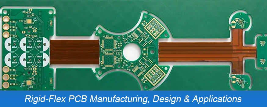
From aerospace to automotive industrial, medical, and beyond, Flexible, rigid-flex printed circuit boards (PCBs) are making them in an expanding number of different applications. Because of their unique design that combines flexible and rigid Printed Circuit Board (PCB) materials, rigid-flex PCBs provide designers with a variety of advantages over conventional all-flexible or all-rigid PCBs
What is a Rigid-Flex PCB?
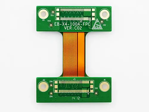
Rigid-flex printed circuit boards are boards that combine the benefits of rigid and flexible board technology. Most rigid flex boards are composed of several different layers of circuit boards that are flexible and are connected to rigid boards either internally or externally in accordance with the design for the use. The flexible substrates are made to maintain the same state of flex. They’re generally shaped into flexible curves during production or installation.
Flexible and rigid PCBs are both available. Flexible PCBs are both flexible and rigid. They help to regulate the flow of electrical current connecting electronic components within different consumer and non-consumer items. The rigid PCBs are more durable than flexible PCBs; however flexible circuit boards are more durable with their flexibility.
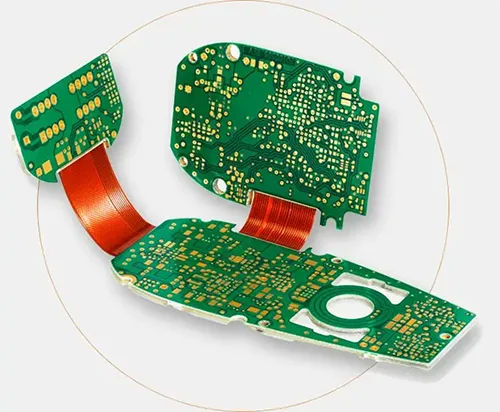
Rigid-flex PCB, is a hybrid model which combines the benefits of PCBs that are flexible and rigid to create a highly efficient board that can maximize the efficiency of its functional use for many applications. It is a great choice due to the combination of flexible and rigid materials that provide an additional increase in reliability and more PCB features.
Material of Rigid-Flex PCBs
Flex-rigid PCBs’ performance depends on the substrate material that flexible dielectric film and flexible adhesive film. Among flexible substrates, it is the most widely used. The flexible dielectric film comprises polyester (Mylar), which is commonly utilized in products with low-end specifications, and polyimide (Kapton), which is the most common kind, and fluoropolymer (PTFE), which is commonly utilized in aerospace and military products.
If the three types of flexible material are evaluated, Polyimide boasts the most dielectric constant, with excellent mechanical and electrical properties, as well as resistance to high temperatures. However, it is also expensive and can easily absorb moisture like polyimide in the sense of its performance. However, polyimide, however, has poor resistance to high temperatures. Polytetrafluoroethylene is primarily used in high-frequency products with low dielectric constant.
Rigid-Flex Product Types
● Single-Sided Flex: Flexible single-sided material with or without shielding or stiffening (one conductor layer).
● Double-Sided Flex: Multilayer layers of flexible material with or without shield(s) or stiffener (more than two conductor layers) with holes plated and HDI.
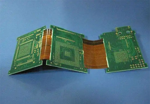
● Multi-layer Flex: Combinations of rigid and flexible materials (more than two conductor layers) , with plated through holes and HDI.
● Multi-layer Rigid and Flexible: Multi-layer rigid and flexible combinations of materials (more than two layers of the conductor) with holes plated through and HDI.
Rigid-Flex PCB Manufacturing Process
Material Preparation (Pre-Clean)
Production panels are chemically cleaned prior to the application of circuit-forming photoresist film to ensure that the film adheres properly. Conveyorized process using advanced handling systems for thin cores to avoid damage to the ultra-thin material cores.
Circuit Pattern Exposure
Photoresist coated panels, overlayed with circuit artwork patterns, the circuit image is transferred from the photoresist-coated panels to the production panels using collimated UV light. Both sides exposed simultaneously if required.
Etch Process
Circuit patterns are chemically etched using specially designed thin-core handling conveyorized systems. Both sides of panels are etched at the same time if necessary.
Drilling Process
High-speed, high-precision, small-hole drilling machines create the required circuit hole patterns for production panels. Laser-based systems are available to meet extremely small holes.
Copper Plating Process
Automated electrolytic copper plating systems deposit copper within plated through holes to form layer-to-layer electrical connections.
Coverlay Application
Polyimide Coverlays aligned and tacked into place on production panels prior to Coverlay lamination process.
Coverlay Lamination
Coverlays are laminated to panels of production under pressure, and heat in order to ensure adhesion.
Stiffener Application
Additional stiffeners are localized (if needed by a specific design) and placed in alignment prior to lamination using pressure, heat, and vacuum.
Electrical Test
100% netlist-driven electrical test per IPC -ET-652. Continuous testing of all circuits to ensure continuity as well as isolation. Grid and flying probe test systems are utilized.
Final Fabrication
Individual pieces are made of production panels using high-precision male and female punches and die sets. Other options comprise laser cutting, mechanical routing steel rule dies, and chemically milled tools based on the specific requirements of the design.
Rigid-Flex PCB Design Guidelines
The advantages of rigid-flex PCBs have been well documented. There are a number of design guidelines to be adhered to in the process of manufacturing these PCBs. They include:
1. Determine The Number of Layers
Flexible-Rigid PCBs consist of different layers of Flexible and stiff PCB Materials. Therefore, it is important to calculate the exact number of layers needed. It is recommended to speak with the manufacturer of your electronics contract early to ensure that all requirements are satisfied.
2. Heat Sinking
The utmost importance should be placed on having a mechanism for dissipating heat installed. Without it the performance of the device could be affected, and it could cause the destruction of the equipment. The PCB needs to facilitate heat sinking.
3. Material Layup
The arrangement of materials is another important aspect. This involves the following:
● The minimum bend radius is required
● The UL flammability rating
● Impedance control
● RoHS certification
● Mechanical considerations, and much more.
A material’s layout can influence its cost and ability to be manufactured.
Rigid-Flex PCB Applications
Flexible Printed Circuit Boards (PCBs) are becoming increasingly sought-after for many different applications. Their flexibility and strength make them suitable for use in products susceptible to vibration or mechanical stress. They are also used for products with limited space, for example, cell phones, wearables, cell phones, and other electronic devices that must be small. These boards can also be employed to create healthcare devices as well as aerospace applications. Additionally, rigid-flex PCBs can be used to design intricate circuit designs that are impossible or difficult to make with traditional rigid PCBs.
Conclusion
Rigid-flex features a variety of advantages over rigid PCBs and flex PCBs, making them the ideal choice for numerous applications. They’re more durable, possess better electrical efficiency, and have more design flexibility. If you’re thinking about using rigid-flex PCBs for future projects, get in touch with UnitePCB as we are a highly experienced printer circuit manufacturer. We can offer you the top products.


